Method 1 – Finding Pipe Diameter for Pipeline Design Calculations
Steps:
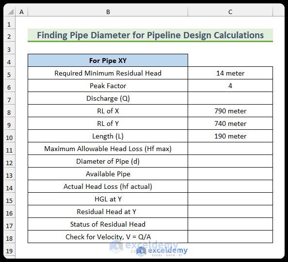
- Enter the given data.
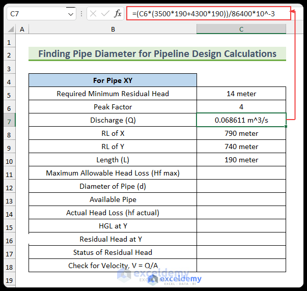
- Use the following formula to find the discharge rate (Q). To find this, multiply the number of people with the water demand and the peak factor. We are converting it to the cubic meter per second unit.
=(C6*(3500*190+4300*190))/86400*10^-3
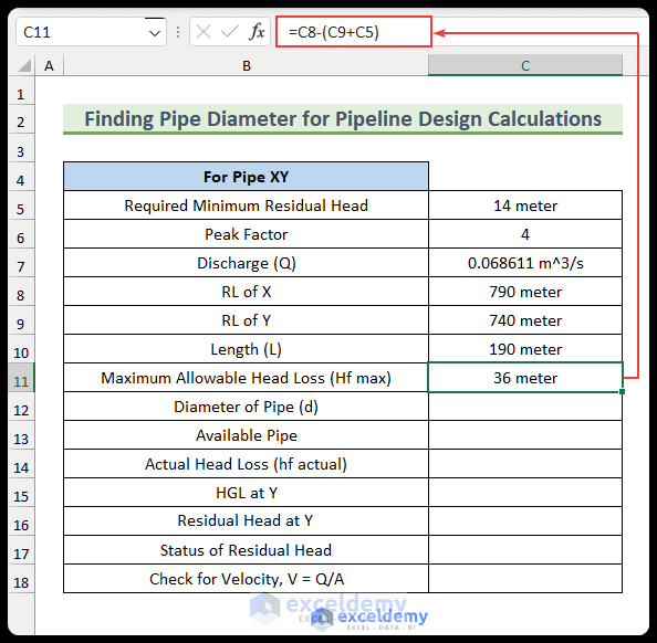
- Insert the following formula to find the maximum allowable head loss:
=C8-(C9+C5)
- Enter the following formula to get the initial diameter of the pipe:
=(10.68*C10/C11*(C7/100)^1.852)^(1/4.87)
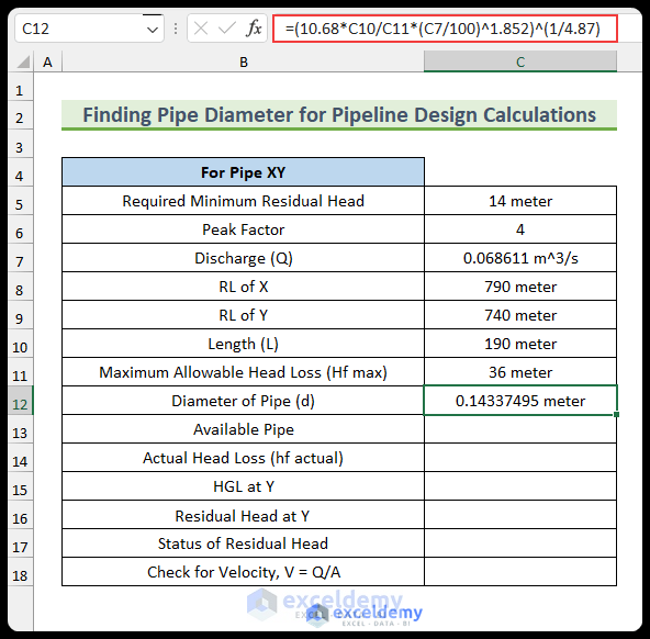
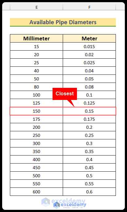
- Select a pipe from the available pipes. The closest pipe in the list below is 0.15 meters. We will select this.
- Find the diameter and the actual head loss from the Hazen-Williams head loss equation:

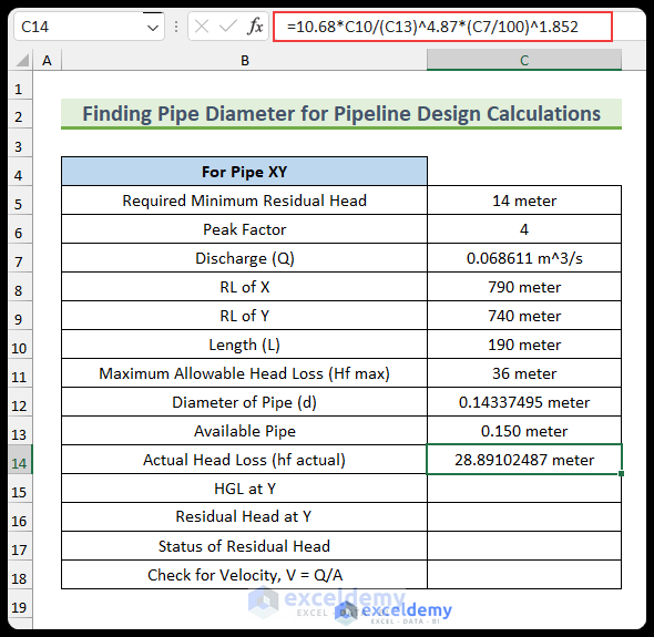
- Use the following formula to find the actual head loss:
=10.68*C10/(C13)^4.87*(C7/100)^1.852
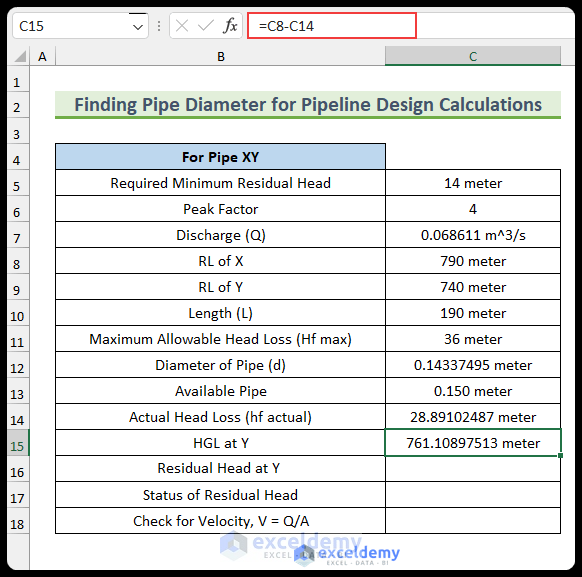
- Enter the following formula to find the hydraulic grade line (HGL):
=C8-C14
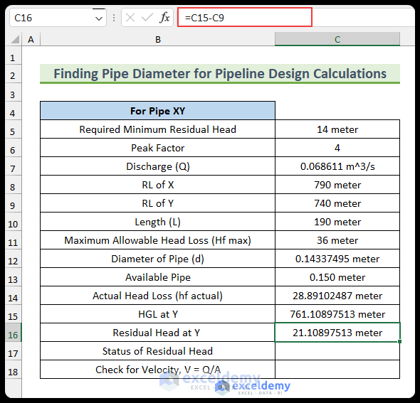
- Enter the following formula to calculate the residual head:
=C15-C9
- Enter the following formula to find the residual status:
=IF(C16>C5,"Good","Bad")
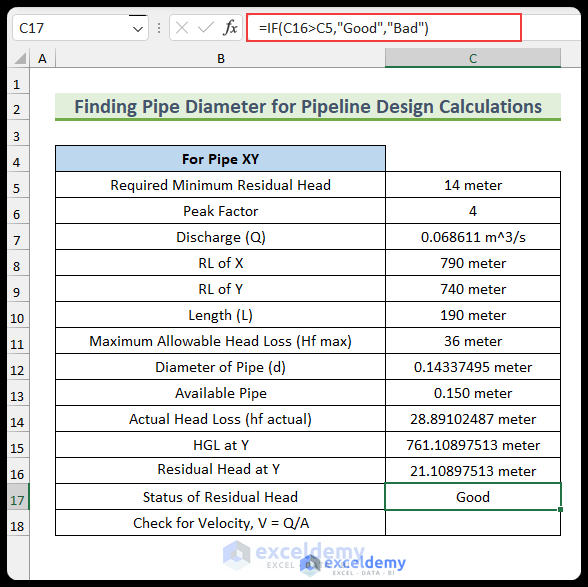
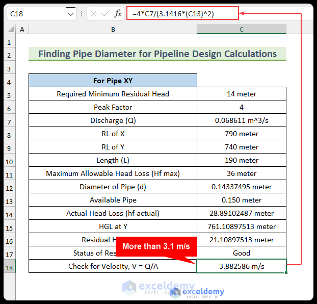
- Enter the following formula to return the flow’s velocity. We can see that the velocity exceeds the limit of 3.1 m/s, so we need to increase the diameter.
=4*C7/(3.1416*(C13)^2)
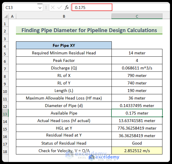
- We have chosen the next pipe diameter of 0.175 meters. Now, the velocity is inside the limit.
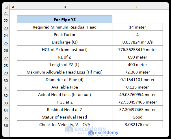
- To calculate the diameter of the pipe for the next region.
Method 2 – Calculating Minimum Pipe Spacing for Pipeline Design
Steps:
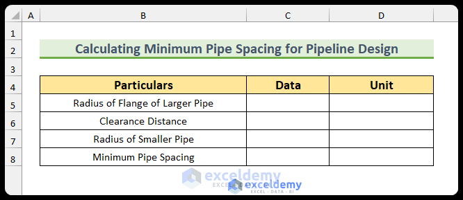
- Create a table to enter the data.
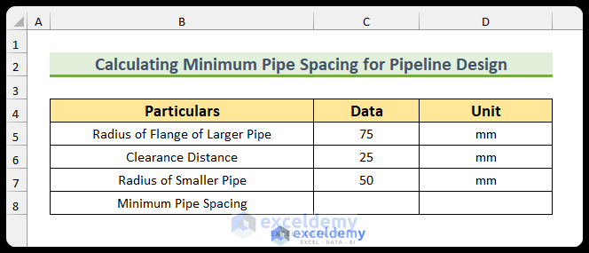
- Enter the given data. The clearance distance is 25 millimeters.
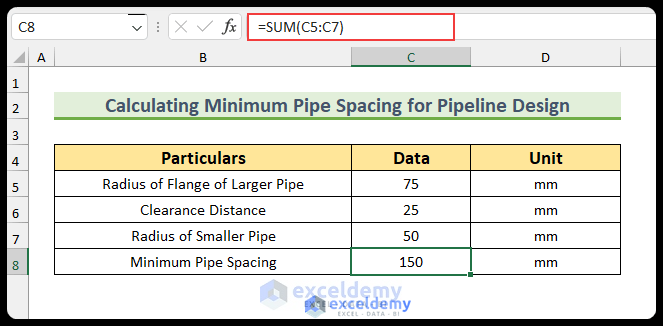
- Enter the following formula to calculate the minimum pipe spacing for the pipeline design calculations:
=SUM(C5:C7)
Download the Practice Workbook
You can download the Excel file from the link below.
<< Go Back to Excel Templates
Get FREE Advanced Excel Exercises with Solutions!

